Custom Camera & Sensor Components CNC Machining
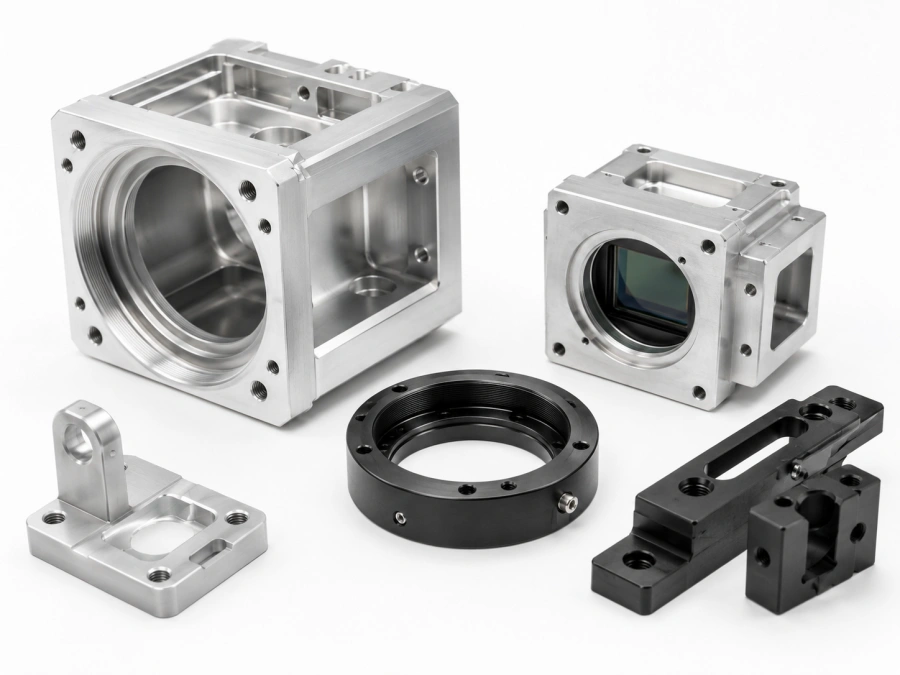
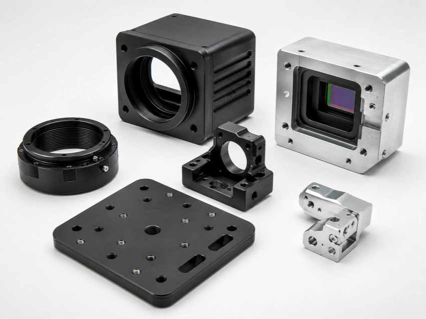
Precision CNC machined camera housings, sensor mounts, lens holders, optical brackets, and inspection equipment components for machine vision, robotics, automation systems, imaging devices, and electronic testing equipment.
Send your 2D drawings, 3D CAD files, material grade, surface finish, and quantity. If the part is used for optical alignment, please mark the critical mounting surfaces clearly.
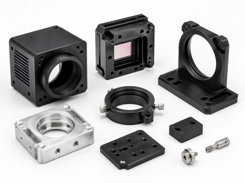
Camera & Sensor Components We Commonly Machine
Camera and sensor parts are usually small, but they often control alignment, mounting stability, heat transfer, and final assembly accuracy. CNCTAL machines custom housings, mounts, brackets, holders, and fixture components based on your drawings and CAD files.
Camera Housings
Custom aluminum camera housings, covers, and compact enclosures for machine vision cameras, inspection equipment, imaging devices, and electronic modules.
- Thin-wall CNC milling
- Internal pockets and mounting bosses
- Black anodizing or clear anodizing
Sensor Housings
Protective housings and small enclosures for sensor modules, with mounting holes, cable openings, sealing features, and internal assembly pockets.
- Accurate mounting hole positions
- Clean edges for electronic assembly
- Prototype and low-volume production
Lens Mounts & Holders
CNC machined lens holders, mounting rings, optical locating parts, and threaded structures where concentricity and surface accuracy can affect alignment.
- Threaded lens features
- Concentricity and fit control
- Low-reflection black finish
Camera & Sensor Brackets
Precision brackets, support blocks, mounting plates, and positioning parts used to fix cameras or sensors inside automation systems and inspection machines.
- Flat reference surfaces
- Threaded mounting holes
- Stable positioning structures
Heat Dissipation Components
Aluminum camera covers, sensor housings, and module parts with cooling grooves, fins, lightweight pockets, or heat-transfer surfaces.
- Cooling fins and milled grooves
- Aluminum 6061 or 7075
- Lightweight structure design
Inspection & Test Fixtures
Custom fixture components for camera testing, sensor calibration, optical alignment, assembly positioning, and electronic module inspection.
- Locating holes and reference faces
- Small batch fixture machining
- Assembly and calibration support
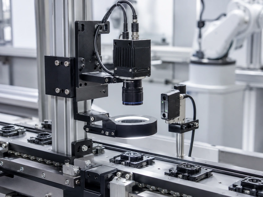
Where Camera & Sensor Components Are Used
Camera and sensor components are used in equipment where accurate positioning, stable mounting, clean assembly, and reliable surface finishing matter. These parts are common in machine vision systems, automation lines, robotics, optical inspection equipment, and electronic testing devices.
Machine Vision Systems
Camera housings, lens holders, mounting plates, and brackets for inspection, measurement, sorting, and visual recognition equipment.
Robotics
Vision module brackets, compact sensor mounts, positioning blocks, and lightweight camera structures for robotic arms, grippers, and mobile platforms.
Automation Equipment
Sensor housings, camera supports, alignment blocks, and fixture parts used in automated production lines and assembly machines.
Optical Inspection Devices
Precision optical mounts, black anodized parts, lens-related components, and structural parts for inspection and measurement systems.
Medical & Laboratory Devices
Small machined housings, sensor brackets, imaging module parts, and clean assembly components for medical or lab equipment.
Electronics Testing Equipment
Custom fixtures, sensor positioning parts, camera inspection supports, and small precision components for testing and calibration systems.
Case study value: CNCTAL reviews more than the outside shape. For camera and sensor projects, we pay attention to mounting surfaces, hole positions, optical alignment areas, burr control, and surface finish requirements before production.
Why Precision Matters for Camera & Sensor Components
Camera and sensor components are not only simple aluminum blocks or covers. In many assemblies, small errors in mounting holes, lens position, flatness, or surface finish can affect image quality, sensor stability, heat control, and final equipment performance.
Mounting Hole Accuracy
Camera modules, sensors, PCBs, and brackets often rely on small mounting holes. Hole position and thread quality must be controlled for repeatable assembly.
Optical Alignment
Lens mounts, sensor seats, and locating faces may affect optical alignment. These features need careful machining and inspection based on the drawing.
Flatness of Mounting Surfaces
Flat mounting faces help keep cameras, sensors, lenses, and electronic modules stable during assembly and use.
Low-Reflection Surface Finish
Black anodizing, bead blasting, and matte finishes are often used to reduce reflection in optical and imaging assemblies.
Heat Dissipation
Camera and sensor housings may include cooling fins, pockets, slots, or thin-wall structures to help manage heat in compact equipment.
Burr and Cleanliness Control
Burrs, sharp edges, chips, and oil residue can affect optical parts, electronics, cable routing, and clean assembly.
Features We Review Before Machining
For camera and sensor projects, we check the functional areas first. This helps avoid problems during assembly, anodizing, and final equipment testing.
- Lens mount diameter, thread, and locating face
- Sensor seat, PCB mounting holes, and internal pockets
- Flatness and perpendicularity of critical mounting surfaces
- M2, M2.5, M3, and other small threaded holes
- Black anodized or low-reflection surface requirements
- Thin-wall areas, cooling fins, and lightweight structures
Small Details Can Affect Final Image and Sensor Performance
In a camera or sensor assembly, the housing, bracket, and mount often decide how well the optical module is positioned. A clean machined surface, accurate hole pattern, stable locating face, and consistent surface finish can make the difference between easy assembly and repeated adjustment.
Machining Challenges for Camera & Sensor Components
Camera and sensor parts often combine thin walls, small threaded holes, internal pockets, optical mounting features, and surface finishing requirements. The machining process needs to consider both dimensional accuracy and final appearance, especially when black anodizing or clean assembly is required.
Precision Starts Before Cutting
Before machining camera or sensor components, we review thin-wall areas, critical locating faces, small threaded holes, surface finish notes, and anodizing requirements. This helps reduce deformation, burrs, and assembly problems.
Thin-Wall Housing Deformation
Camera housings and sensor enclosures often have pockets, windows, and thin walls. Tool pressure, clamping force, and machining sequence must be controlled to reduce deformation after material removal.
Optical Alignment Features
Lens seats, sensor locating faces, mounting holes, and reference surfaces need careful machining because small errors may affect the position of the optical module or sensor assembly.
Small Threads and Fine Holes
M2, M2.5, M3, and other small threaded holes are common in camera and sensor parts. Thread depth, burr control, and hole position need attention to avoid assembly issues.
Black Anodizing Consistency
Many optical and machine vision parts require black anodizing to reduce reflection. Surface preparation, sharp edges, masking areas, and cosmetic surfaces should be reviewed before finishing.
Burr Control and Clean Assembly
Burrs around holes, slots, pockets, and thread openings can affect PCB assembly, lens fitting, cable routing, or sensor installation. Clean edges and careful deburring are important for these components.
Review Functional Surfaces
We identify optical mounting faces, PCB seats, sensor locating areas, and threaded holes that may affect final assembly.
Control Clamping and Sequence
Thin-wall housings and lightweight parts need suitable clamping, cutting paths, and machining order to reduce distortion.
Check Edges and Surface Areas
We review burrs, sharp edges, cosmetic surfaces, and black anodizing requirements before sending parts to surface finishing.
CNCTAL Machining Capabilities for Camera & Sensor Components
Camera and sensor components often require accurate milling, small threaded holes, thin-wall machining, surface finishing, and clean edge control. CNCTAL supports custom camera housings, sensor mounts, optical brackets, lens holders, and test fixture parts from prototype samples to low-volume production.
3-Axis CNC Milling
Suitable for camera brackets, sensor mounts, covers, fixture plates, and aluminum housings with pockets, slots, threaded holes, and flat mounting surfaces.
4-Axis CNC Machining
Useful for side holes, multi-face machining, curved surfaces, cable openings, and camera or sensor parts that need fewer setups.
5-Axis CNC Machining
Applied to complex optical mounts, compact brackets, angled features, and parts with multiple critical surfaces or difficult tool access.
Small Hole Drilling & Tapping
M2, M2.5, M3, and other small threaded holes for camera covers, PCB mounting, sensor modules, lens holders, and compact assembly parts.
Thin-Wall Housing Machining
Machining for lightweight camera housings, sensor enclosures, internal pockets, windows, cable openings, cooling slots, and heat dissipation structures.
Surface Finishing Support
Black anodizing, clear anodizing, bead blasting, sand blasting, passivation, polishing, powder coating, and laser marking can be arranged when required.
Our Process for Camera & Sensor Parts
Before machining, we review the part as an assembly component, not only as a single metal block. This helps us understand which features affect optical position, sensor stability, and final installation.
- Review 2D drawing, 3D CAD file, material, tolerance, and surface finish notes.
- Identify optical mounting faces, sensor locating areas, PCB holes, and thread details.
- Plan the machining sequence, clamping method, tool path, and deburring process.
- Check critical dimensions, hole positions, threads, flatness, and finish before shipment.
Machining Details We Pay Attention To
For camera housings and sensor mounts, small details can affect assembly and use. These are the areas we normally confirm before production.
Materials and Surface Finishes for Camera & Sensor Parts
Camera and sensor components often require a balance of lightweight structure, stable machining accuracy, clean appearance, and suitable surface finish. Aluminum is commonly used for housings and mounts, while stainless steel, brass, copper, and engineering plastics may be selected for special functional parts.
Common Materials
The right material depends on strength, weight, thermal behavior, corrosion resistance, insulation, and final assembly requirements.
Surface Finishing Options
Finishing is important for both appearance and function. For optical and imaging equipment, surface reflection, color consistency, burr control, and clean assembly should be considered early.
Black Anodizing
Common for camera parts, optical mounts, and machine vision components to reduce reflection and improve appearance.
Clear Anodizing
Used for aluminum housings and brackets when corrosion protection and natural aluminum appearance are preferred.
Bead Blasting
Provides a matte surface before anodizing and helps create a cleaner, more consistent appearance.
Hard Anodizing
Suitable for selected aluminum parts needing better wear resistance or a more durable surface.
Passivation
Used for stainless steel sensor parts, pins, brackets, and clean equipment components requiring better corrosion resistance.
Laser Marking
Applied for part numbers, orientation marks, batch codes, or product traceability when required.
Black Anodizing for Low-Reflection Optical Assemblies
Many camera and sensor components use black anodizing because it gives aluminum parts a clean finish and helps reduce unwanted reflection inside optical or machine vision systems. For these parts, surface preparation and edge quality before anodizing are important.
- Suitable for camera housings, optical brackets, lens holders, and sensor mounts.
- Bead blasting can be used before anodizing for a more matte surface.
- Cosmetic surfaces, sealing areas, and masked areas should be marked on the drawing.
- Sharp edges and burrs should be controlled before surface finishing.
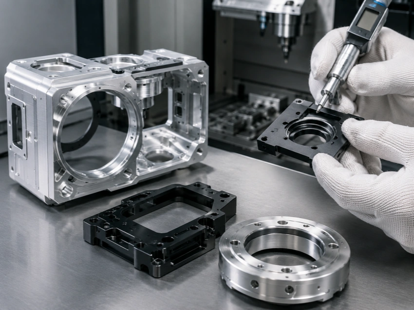
Quality Control for Camera & Sensor Components
For camera and sensor components, quality control is not only checking the outside size. Mounting holes, optical reference surfaces, PCB seats, thread quality, flatness, surface finish, and burr control all affect final assembly and equipment performance.
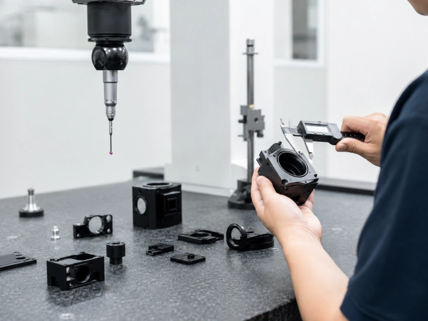
Inspection Focus for Imaging Components
Camera housings, sensor mounts, and optical brackets usually have several critical functional areas. We check the features that affect positioning, alignment, fastening, and final assembly before shipment.
Hole Position
Mounting holes for cameras, sensors, PCBs, brackets, and covers are checked according to the drawing tolerance.
Flatness
Critical mounting surfaces and optical reference faces are checked to support stable assembly and positioning.
Thread Quality
Small threaded holes such as M2, M2.5, and M3 are checked to reduce assembly problems and screw damage.
Lens Mount Features
Lens-related diameters, pockets, shoulders, threads, and locating faces are reviewed when they are marked as critical.
Surface Finish
Black anodized, bead blasted, polished, or cosmetic surfaces are checked for scratches, stains, sharp edges, and visual consistency.
Burr Control
Burrs around holes, slots, pockets, cable openings, and thin edges are controlled before finishing and final packing.
Inspection Tools We Commonly Use
Different camera and sensor components need different inspection methods. For normal projects, we use practical inspection tools during production and final checking. For tighter optical or assembly requirements, additional inspection reports can be arranged.
- CMM for critical hole positions and complex dimensions
- 2D vision inspection for profiles, holes, and small features
- Height gauge for step height and mounting surface checks
- Micrometer and caliper for standard dimensional inspection
- Thread gauge for small internal and external threads
- Surface roughness check when Ra value is specified
Drawing tip: If your camera or sensor part has optical alignment features, PCB mounting points, lens-related holes, critical flat surfaces, or cosmetic anodized areas, please mark them clearly on the drawing. This helps us set the correct machining and inspection priorities before production.
What to Send for a Camera & Sensor Component Quotation
A good RFQ helps us understand the part function before quoting. For camera and sensor components, the material, surface finish, hole position, optical mounting areas, and assembly notes can all affect machining cost, lead time, and inspection planning.
Typical Projects We Support
CNCTAL works with engineers, machine builders, robotics teams, and equipment manufacturers on custom camera and sensor parts from early prototypes to low-volume production.
Recommended RFQ Information
Please send drawings and project details as clearly as possible. If some details are not confirmed yet, our engineering team can review the files and help identify the key questions before quotation.
- 2D drawing with tolerances, threaded holes, finish notes, and critical dimensions
- 3D CAD file such as STEP, STP, IGS, IGES, STL, or other common formats
- Material grade such as Aluminum 6061, 7075, stainless steel, brass, copper, POM, or PEEK
- Surface finish requirement, especially black anodizing, bead blasting, or laser marking
- Critical optical surfaces, lens mount areas, sensor locating faces, or PCB mounting holes
- Quantity for prototype, low-volume batch, or repeat production
Mark Critical Alignment Areas
If the part holds a lens, sensor, or camera module, mark the locating face, hole pattern, flatness requirement, and related tolerance clearly on the drawing.
Confirm Black Anodizing Early
For low-reflection camera or optical parts, confirm black anodizing, bead blasting, cosmetic surfaces, and any masked areas before production starts.
Send Multiple Quantity Levels
Sending quantities such as 1 pc, 10 pcs, 50 pcs, or 200 pcs helps compare prototype and batch production pricing more clearly.
Camera & Sensor Components Machining FAQs
Common questions about CNC machined camera housings, sensor mounts, optical brackets, lens holders, black anodizing, prototype machining, and quotation requirements.
Can you machine custom camera and sensor components from drawings?
Yes. CNCTAL machines custom camera housings, sensor housings, lens holders, optical mounts, brackets, covers, heat dissipation parts, and test fixture components based on 2D drawings, 3D CAD files, or samples.
What materials are suitable for camera housings and sensor mounts?
Aluminum 6061 is commonly used for camera housings, sensor mounts, and lightweight brackets. Aluminum 7075 can be used for stronger structural parts. Stainless steel, brass, copper, POM, and PEEK may also be selected for special mounting, thermal, conductive, insulating, or high-performance applications.
Can you make black anodized camera and optical parts?
Yes. Black anodizing is commonly used for camera housings, optical mounts, lens holders, and machine vision parts to reduce reflection and improve appearance. Bead blasting before anodizing can also be arranged when a matte surface is required.
Can you machine thin-wall camera housings?
Yes, we can machine thin-wall aluminum housings and compact enclosures. For these parts, we review wall thickness, internal pockets, clamping method, machining sequence, and finishing requirements before production to reduce deformation and cosmetic issues.
Can you control hole position and mounting surface flatness?
Yes. Hole position, flatness, perpendicularity, thread quality, lens mount features, PCB mounting holes, and sensor locating faces can be inspected according to your drawing requirements. Please mark critical optical or assembly surfaces clearly.
Can you machine small threaded holes such as M2, M2.5, or M3?
Yes. Small threaded holes are common in camera and sensor components. We can machine and check M2, M2.5, M3, and other small threads according to the drawing. Thread depth, hole position, and burr control should be clearly defined when they are critical.
Can you support prototype and low-volume camera parts?
Yes. CNCTAL supports one-off prototypes, engineering test parts, small batch camera housings, sensor mounts, optical brackets, and repeat low-volume production. You can send multiple quantities in one RFQ to compare prototype and batch pricing.
What files should I send for a camera or sensor component quote?
Please send a 2D drawing with tolerances and a 3D CAD file such as STEP, STP, IGS, IGES, or STL. Also include material grade, surface finish, quantity, critical optical surfaces, threaded hole requirements, cosmetic surface notes, and any assembly requirements.
Need Custom Camera or Sensor Components?
Send your drawings, CAD files, material grade, surface finish, and quantity. Our engineering team will review the machining details and provide a practical quotation.