
Common CNC Machining Design Mistakes: What Makes Parts Difficult or Impossible to Manufacture?
A CAD model may look perfect on a screen. But once the design reaches the machine shop, some features can become expensive, difficult, slow, or even impossible to machine.
In CNC machining, good design is not only about part functionality. It is also about manufacturability. A design that ignores machining limits can increase cost, extend lead time, create inspection problems, or force unnecessary redesigns.
Many CNC machining problems are avoidable if engineers consider tool access, wall thickness, tolerance requirements, internal radii, clamping, and surface finishing early in the design stage.
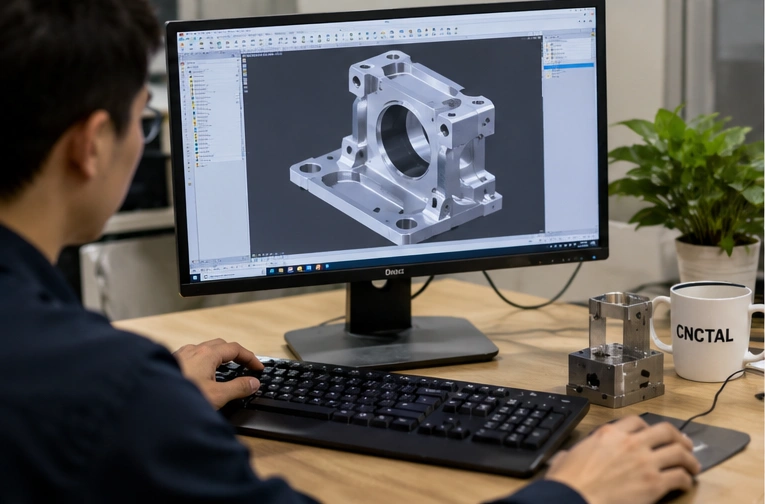
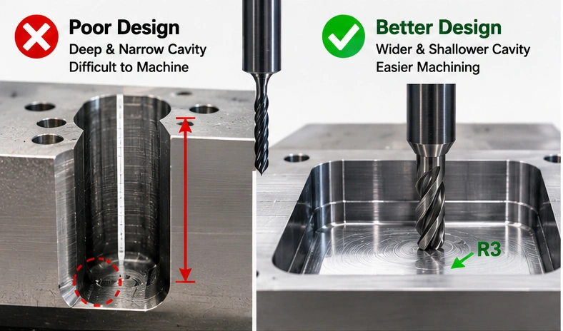 Image 1: CNC manufacturability review helps identify design risks before production.
Why CNC Design for Manufacturability Matters
Modern CAD software makes it easy to create complex geometry. However, CNC machining is still limited by cutting tools, machine access, material behavior, fixturing, and inspection requirements.
- Deep pockets may require long and unstable cutting tools
- Sharp internal corners cannot be made with standard round end mills
- Excessively tight tolerances increase cost and inspection time
- Thin walls may vibrate, deform, or crack during machining
- Hidden features may have no practical tool access
A manufacturable CNC design is not always the simplest CAD model. It is the design that meets function requirements while allowing reliable machining, inspection, and finishing.
1. Deep Narrow Cavities
The problem
One of the most common CNC design mistakes is creating deep, narrow pockets or cavities. These features may look clean in CAD, but they often require long, small-diameter cutting tools.
Long tools are less rigid during cutting. This can cause tool deflection, chatter marks, poor dimensional accuracy, poor surface finish, and increased machining time.
Typical machining risks:
- Tool deflection
- Chatter marks
- Poor surface finish
- Higher tool breakage risk
- Longer machining cycle
Better design practice:
Keep cavity depth reasonable whenever possible. A practical guideline is to avoid pocket depths greater than about 4× the tool diameter. If the cavity must be deep, increase the width or redesign the feature to improve tool access.
2. Sharp Internal Corners
The problem
Many CAD models include perfectly sharp internal corners. In CNC milling, this is usually not realistic because cutting tools are round. Standard end mills naturally create internal corner radii.
Trying to create sharp inside corners often requires very small tools, additional operations, or special solutions. This increases cost and machining time.
Better design practice:
- Add internal corner radii where possible
- Use larger radii to allow stronger cutting tools
- Use dog-bone relief for square mating parts when necessary
- Avoid sharp internal corners unless they are truly functional
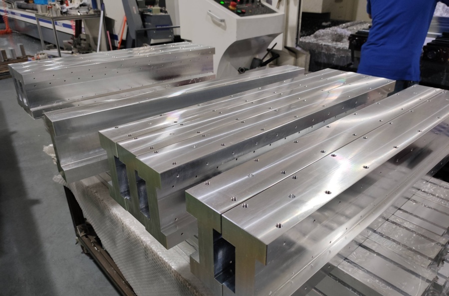
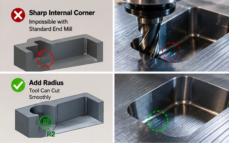 Image 2: CNC milling tools are round, so internal corners should include proper radii or relief features.
3. Unrealistically Tight Tolerances Everywhere
The problem
Tight tolerances are important for functional features, but applying very tight tolerances to every surface is a costly mistake.
For example, specifying ±0.005 mm on cosmetic or non-critical surfaces may add cost without improving real function.
Why this increases cost:
- More careful machining parameters
- Additional inspection time
- Higher scrap risk
- More setups or secondary operations
- Longer lead time
Better design practice:
Apply tight tolerances only to functional features such as bearing seats, mating surfaces, precision holes, sealing faces, and assembly interfaces. Use standard machining tolerances for general geometry.
4. Thin Walls That Are Difficult to Machine
The problem
Very thin walls are difficult because they lack rigidity. During machining, thin sections may vibrate, bend, distort, crack, or move away from the cutting tool.
Thin-wall problems are common in aluminum housings, plastic enclosures, lightweight brackets, and small precision components.
Better design practice:
- Increase wall thickness where possible
- Add support ribs if lightweight design is required
- Avoid tall thin walls without support
- Consider material behavior after machining
As a general reference, metal walls above 0.8 mm are usually safer than extremely thin sections, while many plastic parts benefit from wall thickness above 1.5 mm. Actual limits depend on geometry, material, and part size.
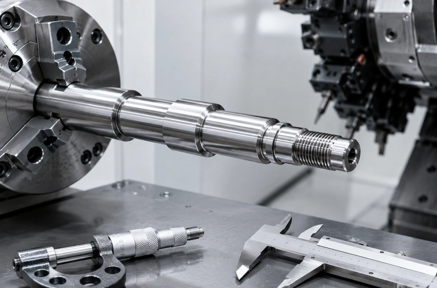
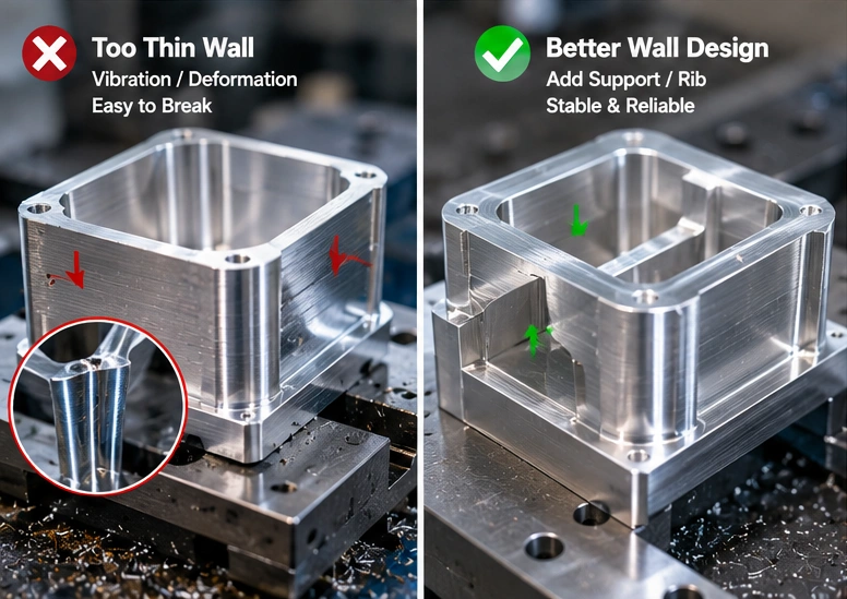 Image 3: Thin walls can deform or vibrate during CNC machining if the design lacks enough rigidity.
5. Threads That Are Too Small, Too Deep, or Poorly Located
The problem
Thread design is often overlooked. Very small threads, overly deep threads, or threads placed in difficult-to-reach locations can create machining problems.
Excessive thread depth may increase machining time without providing meaningful additional strength.
Better design practice:
- Use standard thread sizes whenever possible
- Avoid unnecessary deep threaded holes
- Provide enough tool clearance around threaded features
- Use practical thread engagement based on load requirements
In many cases, 1–1.5× thread diameter engagement is sufficient for normal mechanical assemblies.
6. Hidden Internal Features With No Tool Access
The problem
Some CAD models include internal pockets, undercuts, or enclosed features that cannot be reached by cutting tools.
A CNC machine can only cut where the tool can physically reach. Even 5-axis machining has tool length, tool diameter, holder clearance, and collision limitations.
Better design practice:
- Think about machining direction during design
- Avoid fully enclosed internal features unless another process is planned
- Split complex designs into multiple machined components if needed
- Discuss difficult geometry with the manufacturer early
7. Ignoring Workholding and Clamping Requirements
The problem
Every CNC part must be held securely during machining. If the design provides no stable clamping surfaces or reference faces, the manufacturer may need custom fixtures or additional setups.
Common workholding issues:
- No flat reference surfaces
- Irregular shape with poor clamping area
- Thin unsupported sections
- Features too close to clamping zones
Better design practice:
Add reference faces, fixture points, machining tabs, or stable locating geometry where possible. Good workholding reduces cost and improves repeatability.
8. Designing Without Considering Surface Finishing
The problem
Surface finishing can affect dimensions, appearance, assembly fit, and production sequence. Processes such as anodizing, powder coating, plating, and black oxide should be considered during design.
Typical finishing-related issues:
- Coated holes become too tight
- Threads become difficult to assemble
- Mating surfaces lose required clearance
- Cosmetic surfaces show unexpected tool marks
Better design practice:
Identify critical surfaces before finishing. Allow dimensional compensation for coating thickness when necessary, especially for holes, threads, sliding areas, and mating features.
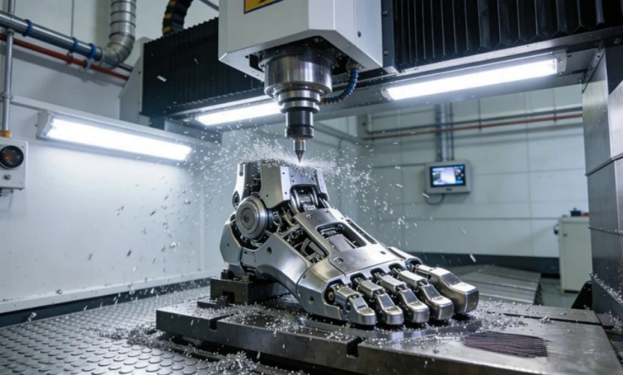
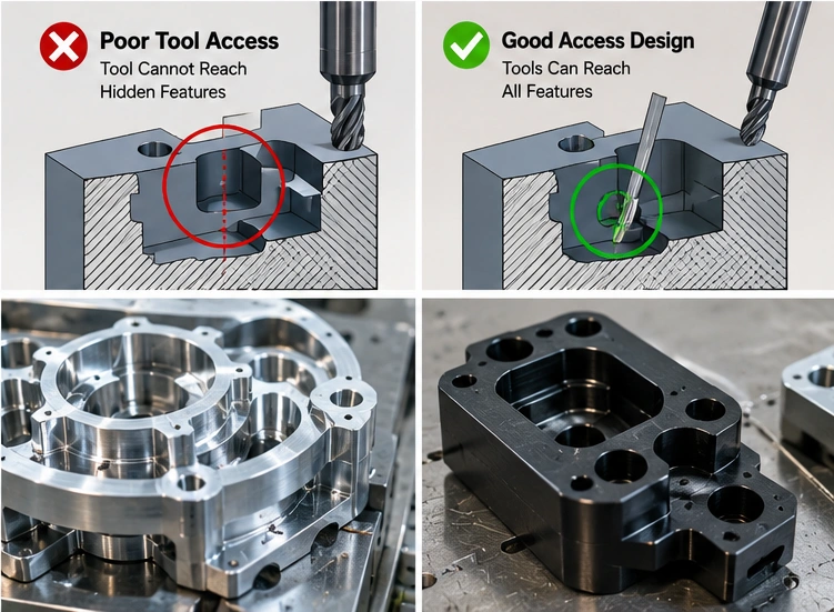 Image 4: Surface finishing should be considered early because coatings can affect fit, appearance, and final performance.
9. Overcomplicated Geometry Without Functional Benefit
The problem
Complex geometry is easy to create in CAD, but every added feature may increase toolpaths, programming time, setup complexity, inspection work, and machining cost.
Decorative features on hidden surfaces, unnecessary small fillets, and complex contours without real functional value often make parts more expensive than they need to be.
Better design practice:
Keep geometry as simple as function allows. Good engineering is often about intelligent simplification, not unnecessary complexity.
Quick Checklist: CNC Design Mistakes to Avoid
| Design Issue | Machining Problem | Better Practice |
|---|---|---|
| Deep narrow cavities | Tool deflection, chatter, poor finish | Increase width or reduce depth |
| Sharp internal corners | Standard round tools cannot create sharp inside corners | Add internal radii or dog-bone relief |
| Tight tolerances everywhere | Higher cost, inspection time, scrap risk | Apply tight tolerances only to critical features |
| Thin walls | Vibration, deformation, cracking | Increase wall thickness or add support ribs |
| No tool access | Feature may be impossible to machine | Review machining direction and access |
| Poor workholding | Extra fixtures, low repeatability | Add reference faces or clamping areas |
| Ignoring finishing | Assembly fit or cosmetic issues | Plan coating thickness and surface requirements early |
Final Thoughts
A successful CNC part is not only functional. It must also be manufacturable.
Design decisions that look simple in CAD can become expensive, difficult, or impossible in real machining environments. Deep pockets, sharp internal corners, excessive tolerances, thin walls, hidden features, and poor workholding all affect cost, lead time, and final quality.
By considering CNC machining limitations early, engineers can reduce redesigns, shorten lead times, and improve production reliability.
Need a Manufacturability Review for Your CNC Parts?
CNCTAL helps customers optimize CNC machined parts before production through practical DFM feedback and engineering support.
- CNC design review
- DFM recommendations
- Prototype optimization
- Low-volume and production machining
- Metal and engineering plastic parts
- Tight tolerances up to ±0.01 mm
If you are unsure whether your design is practical for CNC machining, send us your STEP files or drawings. Our engineering team will help identify manufacturability risks before production begins.
Upload CAD for Instant Quote