
Why CNC Parts Warp During Machining: A Simple Guide for Engineers
Warping is a common problem in CNC machining, especially when parts are thin, long, hollow, or made from materials with low stiffness.
A part may look correct in the CAD model but still bend, twist, or move after machining.
This is especially common with thin-wall aluminum parts, large hollow housings, long and narrow plastic parts, and components with uneven material removal.
For mechanical engineers, understanding why CNC parts warp can help reduce risk before production starts.
What Is CNC Machining Warpage?
Warpage means the part changes shape during or after machining.
Typical problems include:
- Bending
- Bowing
- Twisting
- Flatness loss
- Wall movement
- Hole position shift
Sometimes the deformation appears while the part is still clamped.
In other cases, the part looks correct during machining but moves after it is removed from the fixture.
Why Do CNC Parts Warp?
There is usually not one single cause.
Warping is often the result of several factors working together:
- Internal material stress
- Cutting heat
- Clamping force
- Thin-wall geometry
- Uneven material removal
- Low material stiffness
- Long unsupported sections
The thinner and less rigid the part becomes, the easier it is for machining forces and residual stress to change its shape.
1. Internal Stress in the Raw Material
Raw material is not always completely stress-free.
Plate, bar, extrusion, and molded plastic can contain internal stress from:
- Rolling
- Extrusion
- Heat treatment
- Cooling
- Previous forming processes
When CNC machining removes material from one side, the internal stress can become unbalanced.
The part may then bend or twist.
This is one reason a flat aluminum plate can move after large pockets are machined into it.
2. Thin-Wall Aluminum Parts
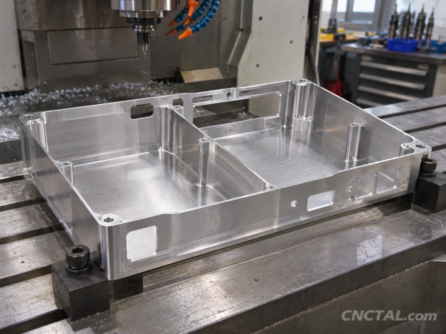
Thin-wall aluminum parts are especially sensitive to deformation.
Examples include:
- Electronic housings
- Lightweight brackets
- Enclosures
- Frames
- Large pockets
- Aerospace structures
As material is removed, the remaining walls become less rigid.
Cutting forces and clamping pressure can then move the walls.
If the wall is very thin, even a small cutting force can cause vibration or temporary deflection.
3. Large Hollow Cavities
Large cavities can also create warping risk.
Imagine machining a large aluminum block into a thin shell.
At the beginning, the raw block is very rigid.
After removing 70–90% of the material, the remaining structure may be much weaker.
If material is removed unevenly from one side, the part may distort.
For this reason, large hollow parts often require:
- Rough machining first
- Stress relaxation time
- Multiple setups
- Balanced material removal
- A separate finishing operation
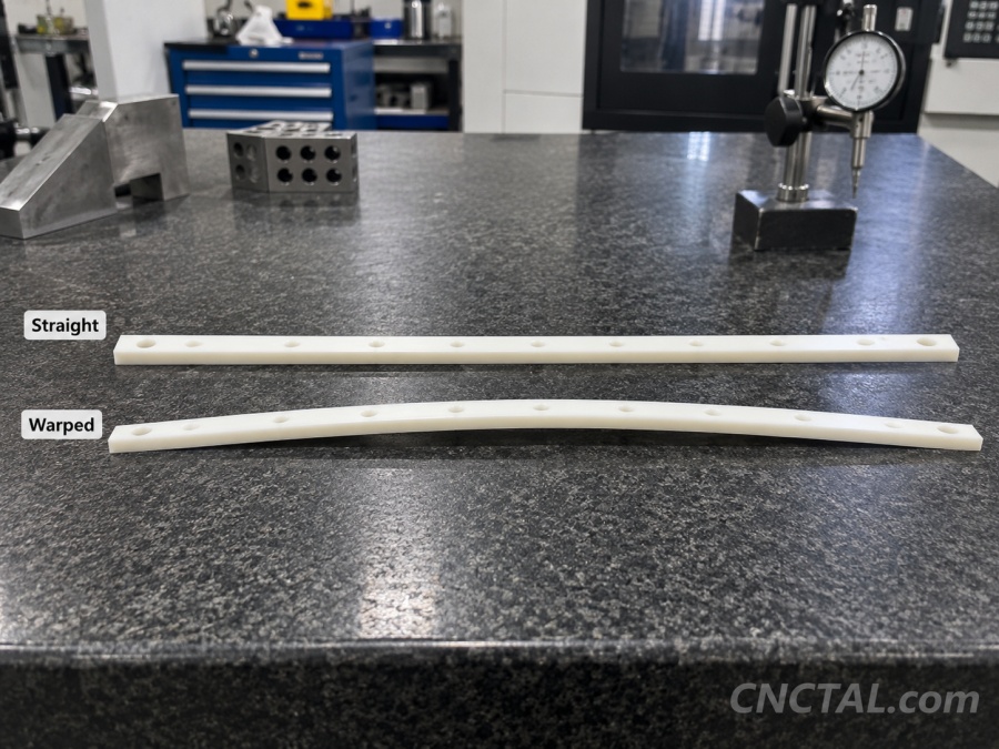
4. Long and Thin Plastic Parts
Plastic parts can be even more difficult than metal when the geometry is long and thin.
Examples include:
- Long guide rails
- Thin strips
- Plastic plates
- Long POM parts
- Narrow PEEK or Nylon components
Plastic has much lower stiffness than aluminum or steel.
It also responds more strongly to heat and clamping pressure.
A long plastic part can bend during machining and remain bent after it is removed from the fixture.
5. Heat During Machining
Machining creates heat.
Metals and plastics both expand when heated, but plastics are generally much more sensitive.
If one area becomes hotter than another, the part can temporarily change shape.
For plastics, heat can also soften the material.
This may cause:
- Bending
- Local deformation
- Poor flatness
- Dimensional instability
6. Clamping Force
Clamping is necessary, but too much clamping force can deform a part.
This is especially important for:
- Thin walls
- Thin plates
- Plastic parts
- Soft aluminum
- Large hollow parts
A part may be forced flat while clamped.
If it is measured in this condition, it may look correct.
But once the clamp is released, the part may spring back.
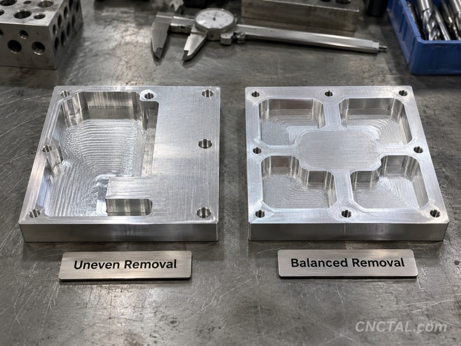
7. Uneven Material Removal
Removing too much material from one side can create an imbalance.
For example, if one side of an aluminum plate is heavily pocketed while the other side remains thick, the part may bend.
A more stable machining strategy is often to remove material gradually and more evenly.
For high-risk parts, rough machining may be completed first, followed by a rest period or stress-relief stage before the final finishing operation.
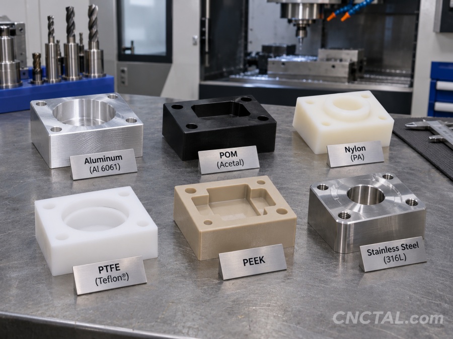
Which Materials Are More Likely to Warp?
Different materials have different levels of deformation risk.
Aluminum
Aluminum is easy to machine, but thin-wall aluminum parts can still warp.
Risk is higher for:
- Large plates
- Thin housings
- Deep pockets
- Parts with heavy material removal
- Extruded material
6061 and 7075 can both deform if the geometry is weak or the machining process is unbalanced.
POM / Acetal
POM is widely used for precision plastic parts, but long and thin POM components can bend significantly after machining.
POM has lower stiffness than metal and higher thermal expansion.
Nylon
Nylon is relatively flexible and can also absorb moisture.
Thin and long Nylon parts may change dimensions or shape more easily than rigid metals.
PTFE
PTFE is very soft and flexible.
It is one of the more difficult engineering plastics to hold to tight flatness or straightness requirements.
PEEK
PEEK is more rigid and dimensionally stable than many engineering plastics, but thin sections can still warp.
Stainless Steel
Stainless steel is much stiffer than plastic, but thin parts can still distort.
High cutting forces and heat can increase risk, especially in thin-wall or highly machined components.
Which Shapes Have the Highest Warping Risk?
Some geometries are naturally more difficult.
High-risk designs include:
- Very thin walls
- Long narrow plates
- Deep open cavities
- Large flat parts
- Uneven cross-sections
- Long plastic strips
- Thin ribs
- Parts with material removed mainly from one side
The combination of thin geometry and difficult material creates the highest risk.
How Engineers Can Reduce Warping Risk
Machining Strategies That Can Help
The CNC supplier may use process controls such as:
- Rough machining before finishing
- Leaving extra material for final passes
- Multiple machining stages
- Flipping the part between operations
- Lower cutting forces
- Sharp cutting tools
- Lighter clamping pressure
- Custom soft jaws
- Stress relief before final machining
For high-risk parts, machining strategy can be just as important as material selection.
A Simple Aluminum Example
Consider two aluminum housings with the same outside size.
Design B has a much higher risk of wall movement, flatness problems, vibration, and post-machining distortion.
Even if both parts use the same aluminum alloy, geometry can make one much more difficult to manufacture.
A Simple Plastic Example
Consider a POM strip that is:
- 500 mm long
- 20 mm wide
- 5 mm thick
Even if the dimensions are simple, the part may bend after machining because it is long, thin, and relatively flexible.
Reducing thickness further or machining a deep slot along one side can make the problem worse.
In this type of part, the main challenge is often not machining complexity. It is dimensional stability.
Can Warping Be Completely Eliminated?
Not always.
For very thin, long, or flexible parts, some deformation may be unavoidable.
The goal is usually to control warping within an acceptable range.
This requires balancing:
- Material selection
- Part geometry
- Machining sequence
- Fixturing
- Tolerance requirements
Practical Design Tips
- Avoid unnecessarily thin walls.
- Avoid very long and narrow plastic sections.
- Use balanced geometry where possible.
- Add ribs or support features to large thin parts.
- Consider material stiffness, not only strength.
- Be careful with large hollow cavities.
- Apply tight flatness requirements only where necessary.
- Ask the CNC supplier about deformation risk before production.
Final Thoughts
CNC part warping is usually caused by a combination of material stress, geometry, heat, clamping, and material removal.
Thin-wall aluminum housings and large hollow parts can distort because their stiffness decreases as material is removed.
Long and thin plastic parts are even more sensitive because plastics have lower stiffness and higher thermal expansion.
Materials such as POM, Nylon, PTFE, and other engineering plastics generally require more attention when the part is long, thin, or asymmetric.
The best way to reduce warping is to consider dimensional stability during the design stage, not only after machining begins.
Concerned About Warping in Your CNC Part?
CNCTAL reviews CNC parts for thin walls, deep cavities, long plastic features, and other deformation risks before production.
If your design contains high-risk geometry, send us your STEP and PDF drawings and our engineering team can review the manufacturability before machining.
Request a CNC Machining Quote