
CNC Machining Surface Finish Guide: Roughness, Tool Marks, and Production Considerations
Surface finish is an important part of CNC machining, especially for components that need good appearance, sealing, sliding contact, accurate fitting, or additional surface treatment.
A CNC-machined part may look smooth to the eye, but its surface still contains very small peaks, valleys, and machining marks left by the cutting tool. These features are usually described using surface roughness, with Ra being one of the most common values shown on engineering drawings.
Understanding CNC surface finish helps designers choose a practical roughness requirement without unnecessarily increasing machining time and production cost.
What Is CNC Surface Finish?
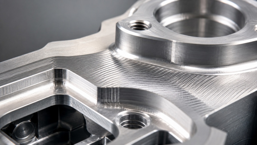
CNC surface finish describes the condition and texture of a machined surface after milling, turning, grinding, or another manufacturing process.
Several factors can affect the final surface quality:
- Cutting tool geometry
- Feed rate
- Spindle speed
- Cutting depth
- Tool sharpness
- Machine rigidity
- Workpiece material
- Cutting direction
- Coolant and machining conditions
Even when two CNC parts have the same dimensions and tolerances, their surfaces can look and feel different depending on how they are machined.
What Does Ra Mean?
Ra stands for arithmetic average surface roughness. It measures the average height variation between the microscopic peaks and valleys of a surface.
Ra is commonly expressed in:
- µm – micrometers
- µin – microinches
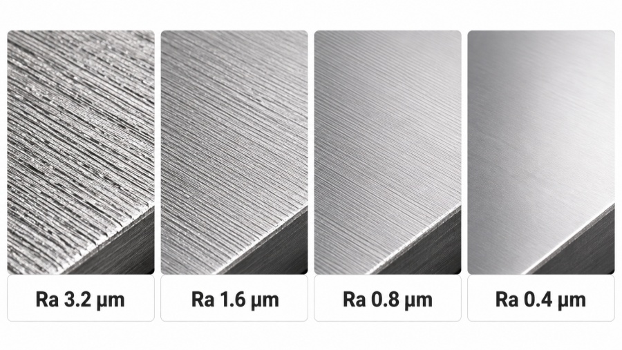
In general, a lower Ra value represents a smoother surface.
| Surface Roughness | General Description | Typical Use |
|---|---|---|
| Ra 6.3 µm | Relatively rough machined surface | Non-critical surfaces and rough machining |
| Ra 3.2 µm | Common CNC machined finish | General mechanical components |
| Ra 1.6 µm | Good-quality machined finish | Precision parts and mating surfaces |
| Ra 0.8 µm | Fine machined finish | Sliding, sealing and precision surfaces |
| Ra 0.4 µm or lower | Very fine finish | May require grinding, polishing or other finishing |
Important: These values are general references. Actual achievable surface finish depends on material, geometry, tooling, machine condition and machining method.
Common CNC Machined Surface Finishes
Ra 3.2 µm
Ra 3.2 µm is a common surface finish for many standard CNC-machined parts.
It is suitable for components where function is more important than cosmetic appearance, such as:
- Machine brackets
- Internal structural components
- Fixtures
- General mechanical parts
- Non-critical mating surfaces
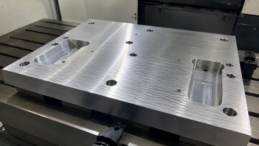
Visible machining marks may still be present, especially on larger flat surfaces.
Ra 1.6 µm
Ra 1.6 µm provides a smoother and cleaner machined surface.
It is often used when a component requires improved appearance, better contact between mating parts, or more controlled surface quality.
For many CNC machining projects, Ra 1.6 µm provides a good balance between surface quality, machining time and production cost.
Ra 0.8 µm
Ra 0.8 µm is considered a relatively fine machined finish.
Achieving this level normally requires more careful machining parameters, sharp finishing tools, lower feed rates and additional finishing passes.
It may be specified for:
- Precision sliding surfaces
- Sealing areas
- Bearing-related surfaces
- High-quality visible components
- Precision shafts and turned parts
Why Do CNC Parts Have Tool Marks?
Tool marks are a normal result of CNC machining.
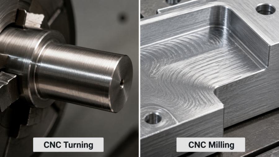
During CNC milling, the rotating cutter moves across the workpiece and leaves small overlapping cutting patterns on the surface.
During CNC turning, the cutting tool moves along the rotating workpiece, usually leaving fine spiral or circular feed marks.
The appearance of these marks depends on:
- Cutter diameter
- Number of cutting edges
- Feed per tooth
- Toolpath direction
- Stepover
- Tool condition
- Machine vibration
- Material properties
A CNC part can meet the specified Ra roughness value while still showing visible machining patterns.
For this reason, surface roughness and cosmetic appearance should not always be treated as the same requirement.
Surface Finish vs. Cosmetic Appearance
This is an important point when designing CNC-machined parts.
For example, a drawing may specify Ra 1.6 µm, but that does not automatically mean the surface will look perfectly uniform or completely free of visible toolpaths.
A large aluminum face may meet the required roughness while still showing cutter patterns under certain lighting conditions.
If appearance is important, the drawing or RFQ should clearly state additional cosmetic requirements such as:
- No visible deep tool marks
- Uniform machining pattern
- Cosmetic surface required
- No scratches or dents
- Specific brushing direction
- Bead blasting before anodizing
This information helps the CNC supplier understand whether the requirement is mainly functional, cosmetic, or both.
How Surface Finish Affects CNC Machining Cost
A finer surface finish usually requires additional machining time.
To improve surface quality, the machinist may need to:
- Reduce the cutting feed rate
- Use smaller finishing cuts
- Add additional finishing passes
- Use dedicated finishing tools
- Reduce tool stepover
- Replace worn cutting tools more frequently
- Control machine vibration more carefully
- Perform additional surface inspection
For example, changing a requirement from Ra 3.2 µm to Ra 1.6 µm may be relatively straightforward for many parts.
However, specifying Ra 0.4 µm on multiple surfaces can significantly increase machining difficulty and production cost.
In some applications, CNC machining alone may not be the most economical method for achieving an extremely smooth surface. Grinding, polishing, lapping or another secondary process may be more suitable.
Material Also Affects Surface Finish
Aluminum
Aluminum alloys such as 6061 and 7075 generally machine well and can achieve a clean surface finish with proper cutting tools and machining parameters.
Sharp tools are important because built-up material on the cutting edge can affect surface quality.
Stainless Steel
Stainless steel can be more difficult to machine smoothly because of its toughness and work-hardening characteristics.
Stable machining conditions, good cutting tools and suitable speeds and feeds are important for achieving a consistent finish.
Brass
Brass generally has excellent machinability and can produce smooth, clean CNC-machined surfaces with relatively little difficulty.
Engineering Plastics
Engineering plastics such as POM, PEEK, Nylon and PTFE require different machining strategies from metals.
Heat generation, material flexibility, tool sharpness and burr formation can all influence the final surface quality.
Surface Finish on CNC Milled and Turned Parts
CNC Milling
Milled surfaces normally show linear, circular or overlapping cutter patterns.
Large flat faces can make these toolpath marks particularly visible. A suitable finishing pass using a face mill or end mill can improve the surface.
CNC Turning
Turned surfaces normally have a regular spiral feed pattern.
Because the cutting process is continuous, CNC turning can often produce very good surface finishes on cylindrical components.
The final result still depends on the tool nose radius, feed rate, workpiece rigidity and cutting conditions.
Do All Surfaces Need the Same Roughness?
Usually, no.
One of the easiest ways to control CNC machining cost is to specify tighter surface requirements only where they are actually required.
For example, a component may require:
- Ra 0.8 µm on a sealing surface
- Ra 1.6 µm on a precision mating surface
- Ra 3.2 µm on general machined surfaces
This is normally more practical than requiring Ra 0.8 µm across the entire component.
Designers should therefore consider the function of each surface before applying a roughness specification.
Surface Finish Before Anodizing or Plating
Surface treatment does not normally remove all machining marks.
Processes such as anodizing, electroless nickel plating and passivation generally follow the existing surface condition of the machined component.
If obvious CNC tool marks are present before finishing, some of them may remain visible afterward.
For cosmetic aluminum components, bead blasting before anodizing is commonly used to produce a more uniform matte appearance.
If final appearance is important, machining requirements and surface finishing requirements should be considered together.
Tips for Specifying CNC Surface Finish
When preparing a CNC drawing or RFQ, it is better to keep surface requirements practical and related to the actual function of the component.
- Do not specify extremely low Ra values unless they are necessary.
- Apply fine surface requirements only to important functional surfaces.
- Separate surface roughness requirements from cosmetic appearance requirements.
- Clearly identify sealing, sliding, bearing and mating surfaces.
- Consider the final anodizing, plating or other surface treatment.
- Consult your CNC machining supplier when you are unsure whether a specified surface finish is practical.
An unnecessarily strict surface roughness requirement can increase machining time, inspection requirements and part cost without improving the actual performance of the component.
Final Thoughts
Surface finish is more than simply making a CNC-machined part look smooth.
It can affect appearance, sealing, friction, wear, assembly and the performance of subsequent surface treatments.
For many general CNC components, Ra 3.2 µm to Ra 1.6 µm is a practical range. Finer finishes such as Ra 0.8 µm or below should normally be specified only when the application requires them.
The best approach is to match the surface finish requirement to the actual function of the part rather than applying the same fine finish to every machined surface.
Need Help With Your CNC Surface Finish Requirements?
CNCTAL manufactures custom CNC machined parts in aluminum, stainless steel, steel, brass, titanium and engineering plastics for prototypes, low-volume production and production quantities.
If your drawing includes specific surface roughness, machining marks or cosmetic requirements, send us your STEP and PDF files. Our engineering team can review the part and recommend a practical machining solution.
Request a CNC Machining Quote