
CNC Machining Internal Corner Radius Guide: Why Inside Corners Need an R Radius
Internal corner radius is an important design consideration for CNC-milled parts.
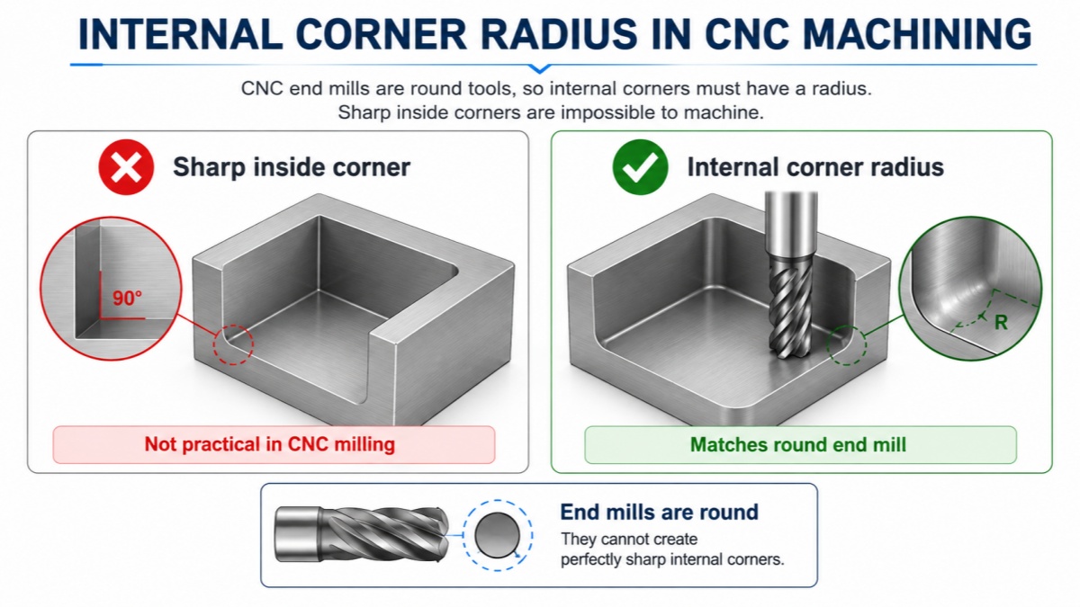
A common mistake in CNC part design is creating perfectly sharp 90-degree internal corners. In most cases, standard CNC milling cannot produce a perfectly sharp inside corner because milling cutters are round.
For this reason, adding the correct internal corner radius, or R radius, can make a part easier, faster, and more economical to machine.
This guide explains why CNC-milled parts need internal radii and how better corner design can improve machining efficiency.
Why CNC Milling Cannot Make Sharp Internal Corners
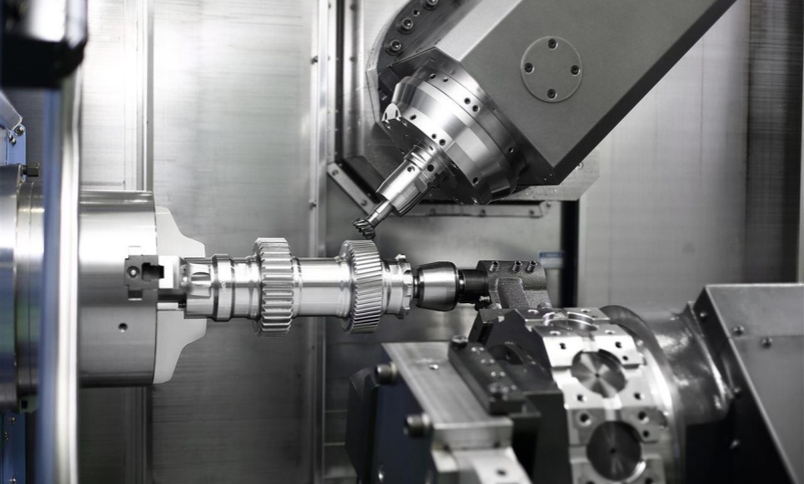
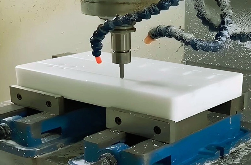
CNC milling uses rotating cutting tools such as end mills.
Because an end mill has a round shape, it naturally leaves a radius in an internal corner.
For example, if a pocket is machined with a 6 mm diameter end mill, the smallest theoretical internal corner radius is approximately 3 mm.
In practice, designers should usually allow some additional clearance instead of designing the radius exactly equal to the cutter radius.
External corners are different. CNC milling can usually produce sharp external edges because the cutting tool approaches the material from the outside.
What Is an Internal Corner Radius?
An internal corner radius is the rounded transition between two inside walls of a CNC-machined feature.
It is commonly shown on engineering drawings as:
- R1
- R2
- R3
- R5
For example, R3 means the inside corner has a radius of 3 mm.
Internal radii are commonly found in:
- Pockets
- Slots
- Internal cavities
- Housings
- Frames
- Fixtures
- Aluminum enclosures
Why Larger Internal Radii Are Easier to Machine
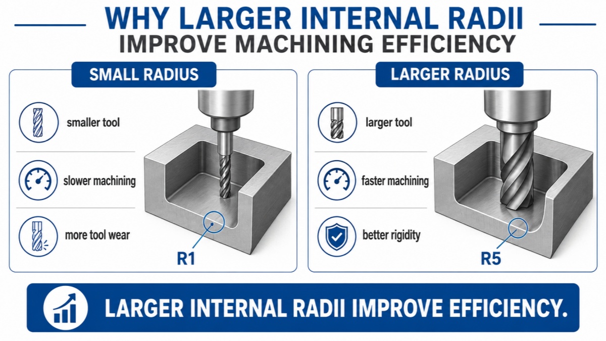
A larger internal corner radius allows the machinist to use a larger cutting tool.
Larger end mills are generally:
- More rigid
- Less likely to vibrate
- Able to remove material faster
- More durable
- Better for maintaining a good surface finish
A very small corner radius often requires a smaller cutter.
Small tools are more flexible and usually require slower cutting speeds and smaller cutting depths. This increases machining time.
For example, if a large pocket can mostly be machined with a 10 mm end mill but the drawing requires R1 corners, the machinist may need to change to a 2 mm cutter just to finish the corners.
That additional operation increases both machining time and tool wear.
Do Not Design the Radius Exactly Equal to the Tool Radius
Another useful design rule is to avoid making the internal corner radius exactly the same as the cutter radius.
For example, machining an R3 corner using a 6 mm end mill forces the cutter to fully engage the corner.
This can increase:
- Cutting forces
- Tool vibration
- Tool wear
- Heat generation
- Risk of poor surface finish
A better approach is to make the designed radius slightly larger than the cutter radius.
| Cutter Diameter | Cutter Radius | Better Design Radius |
|---|---|---|
| Ø4 mm | R2 | R2.5 or larger |
| Ø6 mm | R3 | R3.5 or larger |
| Ø8 mm | R4 | R5 or larger |
| Ø10 mm | R5 | R6 or larger |
These are general design examples rather than fixed rules. The best radius depends on the part geometry, pocket depth, material, and machining strategy.
Pocket Depth Also Matters
Corner radius should not be considered separately from pocket depth.
A deep pocket with a very small internal radius can be difficult to machine.
For example, a 30 mm deep pocket with an R1 internal corner may require a very small and long cutting tool.
A long, small-diameter end mill has lower rigidity and is more likely to:
- Deflect
- Vibrate
- Break
- Produce poor surface finish
- Reduce dimensional accuracy
General design principle: the deeper the pocket, the more helpful a larger internal radius becomes.
How Internal Radius Affects CNC Machining Cost
Corner radius can directly affect CNC machining cost.
A reasonable internal radius allows:
- Larger cutting tools
- Faster material removal
- Fewer tool changes
- Shorter machining cycles
- Lower risk of tool breakage
- Better surface finish
Very small internal radii may require additional finishing operations.
If a small corner does not have an important functional purpose, increasing the radius is often one of the simplest ways to reduce CNC machining cost.
What If a Mating Part Has a Sharp Corner?
Sometimes another component needs to fit inside a CNC-machined pocket.
The mating component may have a sharp square corner, while the CNC pocket naturally has rounded corners.
In this situation, simply reducing the internal radius is not always the best solution.
Use a Chamfer on the Mating Part
Adding a small chamfer to the mating component can provide clearance for the internal radius.
This is often a simple and economical solution.
Use a Larger Corner Radius on Both Parts
If both components can be redesigned, matching compatible corner radii can make manufacturing easier.
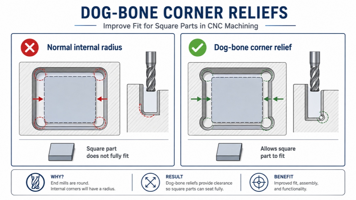
Use Corner Reliefs
Another option is to add relief cuts in the corners.
These are commonly called dog-bone or T-bone reliefs.
They allow a square mating component to fit into a CNC-milled pocket without requiring an extremely small end mill.
What Is a Dog-Bone Corner?
A dog-bone corner adds a small circular relief beyond the normal corner of a pocket.
This gives a square mating part enough clearance to fit completely into the pocket.
Dog-bone corners are commonly used for:
- Plates
- Frames
- Fixtures
- Enclosures
- Interlocking CNC parts
They may not be ideal for cosmetic components because the relief remains visible, but they can be very useful for functional assemblies.
When Is a Small Internal Radius Necessary?
Small internal radii are sometimes unavoidable.
Examples include:
- Compact mechanisms
- Precision mating features
- Existing product designs
- Small slots
- Components with limited space
In these cases, CNC machining can still produce small radii, but additional machining time and smaller tools may be required.
The important point is not to avoid small radii completely. Instead, use them only where they are functionally necessary.
A Simple Design Example
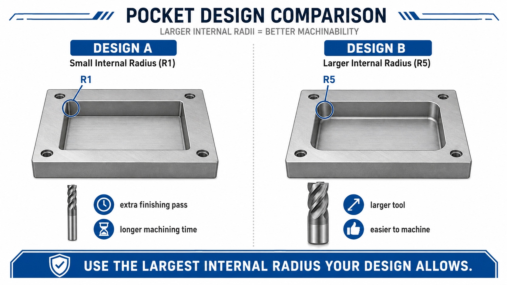
Consider an aluminum enclosure with a large internal pocket.
If the R1 corner has no important functional purpose, Design B will usually be easier and faster to manufacture.
Practical Internal Corner Design Tips
When designing parts for CNC milling, keep these simple guidelines in mind:
- Avoid perfectly sharp internal corners.
- Use the largest internal radius that the design allows.
- Avoid very small radii in deep pockets.
- Do not make the corner radius exactly equal to the cutter radius when possible.
- Use the same radius on multiple corners when possible.
- Consider chamfers or dog-bone reliefs for square mating components.
- Use small internal radii only when they are functionally necessary.
- Ask your CNC supplier if you are unsure about a difficult corner feature.
Simple CNC design rule: use the largest internal corner radius that your part can accept.
This can improve tool rigidity, machining speed, surface quality, and overall manufacturing efficiency.
Final Thoughts
Internal corner radius may look like a small detail on a CAD model, but it can have a significant effect on CNC machining.
Because CNC milling cutters are round, internal corners naturally require a radius.
Using a reasonable R radius allows larger and more rigid tools, reduces machining time, improves surface finish, and can lower production cost.
For most CNC parts, the best approach is simple: use the largest internal corner radius that the design can accept.
Need Help Improving Your CNC Part Design?
CNCTAL manufactures custom CNC-milled parts in aluminum, stainless steel, steel, titanium, brass, and engineering plastics.
If your design contains deep pockets, small internal radii, or difficult corner features, send us your STEP and PDF drawings. Our engineering team can review the design and suggest practical machining improvements.
Request a CNC Machining Quote