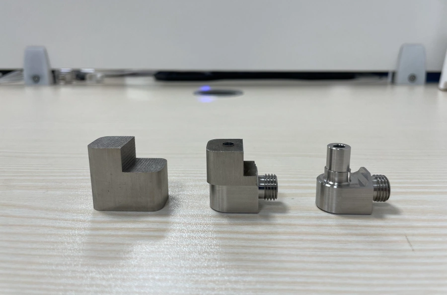

CNC Machining POM Plastic Parts: Benefits, Challenges and Solutions
Learn why POM is widely used for precision plastic components, what causes deformation and dimensional movement during machining, and how manufacturers control heat, residual stress, clamping pressure, and elastic recovery.
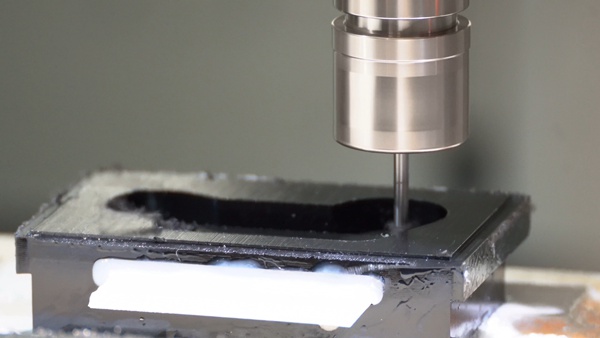
Polyoxymethylene, commonly known as POM or acetal, is a widely used engineering thermoplastic known for its strength, stiffness, low friction, wear resistance, and good dimensional stability.
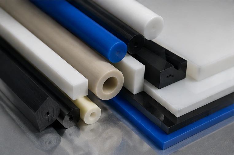
POM is available in two principal forms: POM homopolymer, often associated with the Delrin® trade name, and POM copolymer. Although their properties differ slightly, both materials can be CNC machined into accurate functional parts.
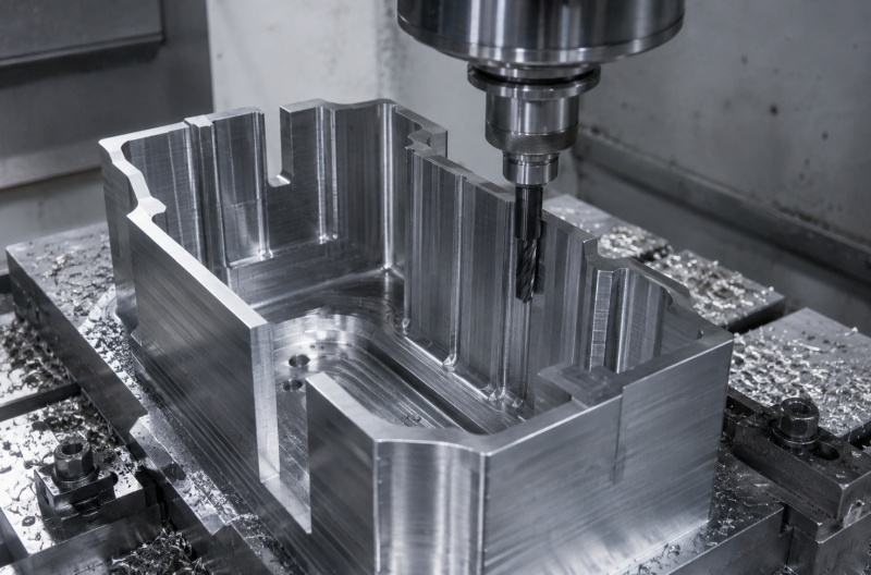
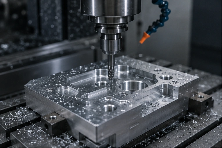
CNC machining POM is an excellent option for prototypes, low-volume production, replacement components, and precision plastic parts that would be difficult or expensive to manufacture with injection molding.
However, POM is not machined in exactly the same way as metal. Its relatively high thermal expansion, elasticity, sensitivity to clamping pressure, and potential internal stress must be carefully controlled.
This article explains the main benefits of CNC machining POM, the most common machining challenges, and practical methods for reducing deformation, cracking, burrs, and dimensional variation.
What Is POM Plastic?
POM is a semi-crystalline engineering thermoplastic with a useful combination of mechanical strength, stiffness, wear resistance, and low moisture absorption.
Common characteristics of POM include:
- Good dimensional stability
- Low coefficient of friction
- Excellent wear resistance
- High stiffness and strength
- Good fatigue resistance
- Low moisture absorption
- Good electrical insulation
- Excellent machinability
These properties make POM suitable for components that require repeated movement, sliding contact, accurate dimensions, or low-friction operation.
Typical CNC-machined POM parts include:
- Gears and sprockets
- Bushings and bearings
- Rollers and guide rails
- Valve components
- Electrical insulators
- Precision spacers
- Automation components
- Medical equipment parts
- Automotive mechanism components
POM-C vs. POM-H
Before machining POM, it is useful to understand the difference between POM copolymer and POM homopolymer.
POM-H
POM homopolymer generally offers:
- Higher stiffness
- Higher tensile strength
- Better fatigue resistance
- Slightly higher hardness
- Good performance under repeated loading
It is commonly selected for highly loaded gears, mechanical components, and precision parts requiring high rigidity.
Large extruded sections may be more sensitive to centerline porosity, and some grades have lower resistance to hot water or alkaline environments.
POM-C
POM copolymer generally provides:
- Better resistance to hot water
- Good chemical resistance
- Lower risk of centerline porosity
- Good dimensional stability
- Reliable general machinability
POM-C is commonly used for industrial machining because it is widely available as stress-relieved rods, plates, and tubes.
Material selection should consider mechanical load, operating temperature, chemical exposure, tolerances, and regulatory needs.
Benefits of CNC Machining POM Parts
Consistent Part Quality
Once the CNC program, cutting tools, workholding method, and inspection process have been established, multiple POM parts can be manufactured with repeatable geometry and dimensions.
This is valuable for medical equipment, aerospace assemblies, electronics, factory automation, automotive systems, and precision instruments.
Fast Prototyping
CNC machining can produce functional POM prototypes directly from engineering-grade rod or plate without requiring an injection mold.
- Shorter development cycles
- Faster design verification
- Lower initial tooling costs
- Earlier detection of design problems
High Dimensional Accuracy
CNC milling and turning can produce accurate holes, pockets, profiles, threads, bores, and mating features in POM.
Achievable tolerance depends on part size, geometry, wall thickness, material grade, workholding, machine stability, and temperature.
Greater Design Flexibility
Design changes can normally be implemented by updating the CAD model and CNC program instead of modifying an expensive injection mold.
This makes machining suitable for custom components, multiple design variants, replacement parts, and bridge production.
No Expensive Mold Required
CNC machining produces components directly from stock material, eliminating dedicated mold costs for prototypes and low-volume production.
It is useful when the design may change, several variants are needed, or delivery time is more important than the lowest possible mass production unit cost.
Good Machined Surface Finish
POM can produce a smooth, clean surface when sharp cutting tools and suitable parameters are used.
Post-processing is often limited to deburring, cleaning, inspection, edge finishing, marking, or assembly.
Complex Part Geometry
CNC machining can produce features such as:
- Precision bores
- Internal and external threads
- Slots and pockets
- Gear teeth
- Contoured surfaces
- Multiple datum faces
Functional Production Parts
POM is not only a prototyping material. Its stiffness, wear resistance, low friction, and fatigue performance make it suitable for many finished mechanical components.
Common examples include gears, rollers, guides, bushings, spacers, low-noise mechanisms, and electrical insulation parts.
Main Challenges of CNC Machining POM
Although POM is generally considered easy to machine, several issues can affect finished-part quality.
Dimensional Movement
POM can expand, contract, or move after machining due to temperature, internal stress, and fixture release.
Heat Buildup
Excessive heat may cause softening, smearing, burr formation, and inaccurate measurements.
Clamping Deformation
Excessive fixture pressure may temporarily bend or compress the part, which then springs back after unclamping.
Residual Stress Release
Removing large amounts of material unevenly may release stress from extruded plate or rod and cause warping.
Other common issues include:
- Burr formation
- Elastic recovery
- Cracking around sharp features
- Difficulty holding tight flatness and parallelism
- Chip wrapping during turning and drilling
Does POM Crack During CNC Machining?
Cracking is possible, but it is not normally the primary problem when machining good-quality POM stock.
Cracks are more likely when:
- The stock contains high residual stress
- Sharp internal corners concentrate stress
- Excessive clamping pressure is applied
- The cutting tool is dull
- Too much heat is generated
- Material is removed unevenly
- Press fits or threads are excessively tight
- Thin and thick sections are poorly balanced
It is not always correct to assume that modified POM is the best choice. Filled or modified grades may improve specific properties, but fillers can also change machinability, stiffness, friction, tool wear, and dimensional behavior. Material selection should be based on the final application.
For critical parts, low-stress or annealed stock may be appropriate. A trial component is also useful when the raw-material condition, part geometry, or required tolerance is uncertain.
Why POM Parts Deform During CNC Machining
POM deformation is generally caused by a combination of four main factors:
Cutting Heat
POM has lower thermal conductivity and higher thermal expansion than most metals. Heat may remain concentrated near the cutting zone, causing temporary expansion and dimensional variation.
Excessive heat can cause:
- Softening
- Smearing
- Poor surface finish
- Burr formation
- Localized deformation
Recommended solutions:
- Use sharp cutting tools
- Use suitable plastic-cutting geometry
- Avoid rubbing and excessive tool engagement
- Maintain effective chip evacuation
- Use compressed air or compatible coolant when required
- Separate roughing and finishing operations
- Allow the part to cool before final inspection
Internal Stress
Extruded POM rods and plates may contain residual stress. When material is removed mainly from one side, the stress distribution becomes unbalanced and the part may bend or twist.
The risk is higher when:
- A large percentage of stock is removed
- The part has thin walls
- The geometry is long, flat, or asymmetrical
- Material is removed mainly from one face
- Tight flatness or parallelism is required
Recommended solutions:
- Use high-quality low-stress stock
- Select stock close to the final dimensions
- Remove material symmetrically
- Alternate machining between opposite sides
- Leave controlled finishing allowance
- Allow stabilization between machining stages
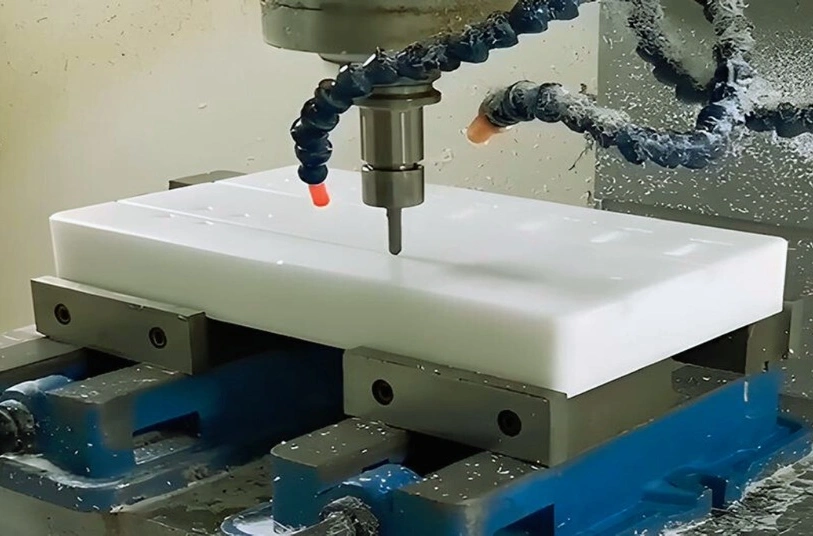
Clamping Pressure
POM is less rigid than aluminum or steel. Excessive clamping pressure can temporarily compress or bend the workpiece.
The part may measure correctly while held in the fixture, but move out of tolerance after it is released.
Recommended solutions:
- Use the lowest secure clamping pressure
- Increase the fixture contact area
- Use soft jaws matched to the part geometry
- Support thin sections near the cutting area
- Use vacuum fixtures for suitable flat components
- Use backing plates or controlled adhesive workholding
- Inspect the part after fixture release
Elastic Recovery
POM has noticeable elasticity compared with metal. Cutting forces may temporarily deflect the material away from the tool, and the surface may recover after the tool passes.
This may affect:
- Bore diameter
- Slot width
- Wall thickness
- Thin ribs
- Turned diameters
- Profile accuracy
Recommended solutions:
- Use sharp cutting tools
- Reduce cutting pressure
- Maintain rigid toolholding
- Leave a controlled finishing allowance
- Use light finishing cuts
- Use a spring pass when appropriate
- Adjust compensation from measured results
Annealing POM Before or During Machining
Annealing can reduce residual stress and improve dimensional stability, particularly for demanding components.
It may be considered for:
- Large or thick components
- Thin-walled finished parts
- Parts requiring substantial material removal
- Long or flat components
- Parts with demanding flatness requirements
- Components with tight dimensional tolerances
Heating and cooling cycles should follow the recommendations for the specific POM grade and stock dimensions. Heating or cooling too quickly may create additional deformation instead of improving stability.
Not every POM component requires annealing. Stable stock, moderate tolerances, balanced machining, and correct workholding may be sufficient for many parts.
Burr Formation in CNC-Machined POM
POM may develop burrs around:
- Hole exits
- Cross holes
- Threads
- Slots
- Thin edges
- Intersecting features
To reduce burr formation:
- Use sharp cutting tools
- Support exit surfaces
- Control feed at breakthrough
- Use suitable drill geometry
- Plan intersecting features carefully
- Add controlled edge chamfers
- Avoid excessive cutting heat
- Deburr without rounding critical edges
Aggressive scraping, sanding, or polishing should be avoided because it may change critical dimensions.
Machining Thin-Walled POM Parts
Thin walls are especially sensitive to heat, cutting pressure, clamping force, and residual stress.
A stable machining sequence may include:
- Start with low-stress material stock.
- Rough-machine both sides where possible.
- Leave additional wall thickness for finishing.
- Allow the component to stabilize.
- Re-fixture the part using low clamping pressure.
- Finish critical surfaces with light cuts.
- Inspect the part after removing it from the fixture.
Thin walls should generally not be finished too early. Keeping extra supporting material during rough machining helps reduce vibration and dimensional movement.
Cooling and Chip Control
POM normally produces continuous or curled chips when machined correctly. During turning and drilling, these chips may wrap around the tool or workpiece.
Good chip control helps prevent:
- Surface scratching
- Tool interference
- Localized heating
- Recutting of chips
- Poor surface finish
- Unexpected machine stoppages
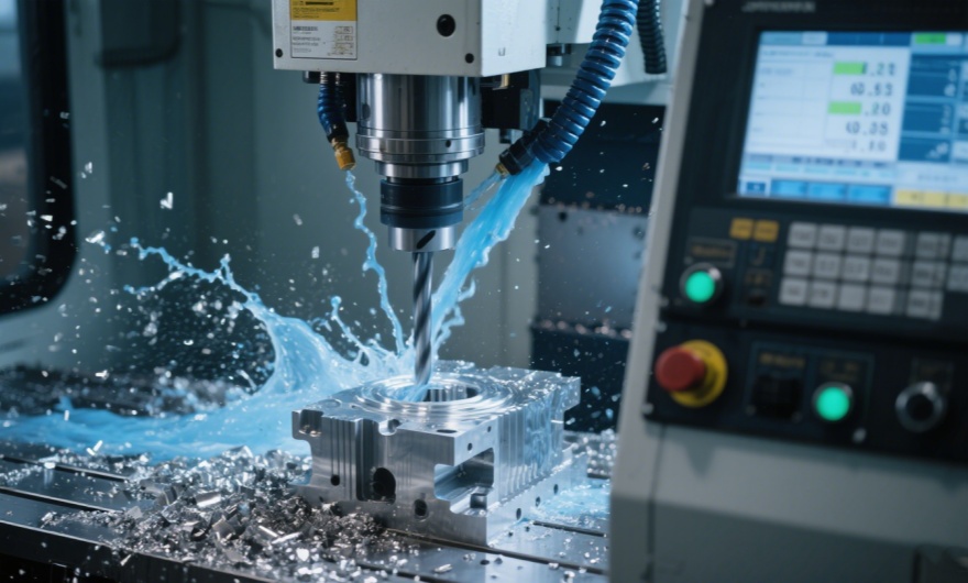
Compressed air is often used for chip evacuation and localized cooling. A suitable water-based coolant may also be used when required, provided it is compatible with the material, machine, and final application.
Recommended CNC Machining Practices for POM
Material Preparation
- Use engineering-grade stock
- Confirm whether it is POM-C or POM-H
- Select stock close to final size
- Consider low-stress material for precision parts
- Inspect raw stock for visible defects
Tool Selection
- Use sharp cutting tools
- Use positive-rake geometry
- Use polished cutting edges when appropriate
- Avoid worn tools that generate heat
- Select suitable drills and reamers for plastics
Machining Strategy
- Use balanced material removal
- Separate roughing and finishing
- Leave sufficient finishing allowance
- Preserve part rigidity during early operations
- Allow stabilization between critical stages
Workholding
- Use the lowest secure clamping force
- Increase fixture contact area
- Use soft jaws and supporting fixtures
- Avoid concentrated point loading
- Measure the part after unclamping
Temperature Control
- Maintain effective chip evacuation
- Avoid long rubbing tool contact
- Allow the workpiece to cool
- Inspect at a stable room temperature
- Use consistent inspection conditions
Inspection
- Inspect after fixture release
- Use appropriate measurement force
- Support flexible parts during inspection
- Define realistic functional tolerances
- Monitor critical dimensions between stages
Realistic Tolerances for CNC-Machined POM
There is no universal tolerance that applies to every CNC-machined POM component.
Tolerance capability depends on:
- Part dimensions
- Wall thickness
- Component geometry
- Material grade
- Starting-stock condition
- Amount of material removed
- Operating and inspection temperature
- Workholding and measurement method
Small and rigid parts may hold relatively tight tolerances. Large plates, thin walls, long components, and heavily pocketed parts are more sensitive to thermal expansion and stress release.
Engineering drawings should distinguish between function-critical dimensions and general dimensions. Applying very tight tolerances to every feature increases cost without necessarily improving the performance of the finished component.
When Should You Choose CNC Machining for POM?
CNC machining is a strong manufacturing choice when:
- You need functional prototypes
- You require low or medium quantities
- The design may still change
- Mold investment is not justified
- Short delivery times are required
- Complex machined features are needed
- Multiple design versions are required
- You need replacement components
For very high production volumes, injection molding may eventually provide a lower unit cost. CNC machining remains valuable for development, bridge production, custom components, and designs that change frequently.
Typical Applications of CNC-Machined POM Parts
Factory Automation
- Conveyor guides
- Rollers
- Sliding blocks
- Positioning parts
- Sensor mounts
Automotive
- Gears
- Bushings
- Clips
- Interior mechanisms
- Motion components
Medical Equipment
- Instrument parts
- Mechanical guides
- Positioning parts
- Equipment housings
- Non-implant components
Electronics
- Insulators
- Connector parts
- Mounting blocks
- Precision spacers
- Device housings
Food Equipment
- Wear strips
- Rollers
- Guides
- Scraper components
- Bushings
Precision Machinery
- Bearings
- Spacers
- Low-friction sliders
- Valve components
- Fixture elements
Conclusion
CNC machining POM is an effective method for producing accurate prototypes, low-volume components, replacement parts, and functional engineering components.
Its main benefits include good machinability, short lead times, design flexibility, smooth machined surfaces, and the ability to manufacture complex geometry without investing in injection-molding tooling.
The primary challenges are cutting heat, internal-stress release, clamping deformation, elastic recovery, burr formation, and dimensional movement.
These issues can be controlled through proper material selection, sharp cutting tools, balanced material removal, staged roughing and finishing, low-pressure workholding, temperature control, suitable finishing allowances, stable inspection conditions, and annealing when genuinely required.
When POM material behavior is considered during design and process planning, CNC machining can produce accurate, reliable, and durable plastic components for a wide range of industrial applications.
Need Custom CNC-Machined POM Parts?
CNCTAL manufactures precision POM-C and POM-H components from your CAD files and technical drawings. We support functional prototypes, low-volume production, replacement parts, and custom engineering plastic components.
Request a CNC Machining Quote